What Is a Ground Anchor Tendon?
About Ground Anchor Tendons
A ground anchor tendon is the load-carrying element within a ground anchor, usually formed from a high-strength steel bar or a group of steel strands. It carries tensile force between the anchor head and a bonded zone within suitable soil or rock.
The tendon forms part of a system that restrains structures against movement or uplift. Its strength, length and protective details are designed alongside the grout, anchorage and surrounding ground.
Where Are Ground Anchor Tendons Used?
Ground anchor tendons are used in retaining walls, excavation support, and foundation restraint. Infrastructure and rail applications include anchored walls beside highways, bridge approaches, railway cuttings and station works. Marine projects may use them to strengthen quay walls or resist uplift beneath dry docks.
Residential, commercial and institutional developments may require anchoring for deep basements, underground car parks and excavations near existing buildings. In the energy sector, applications include dam strengthening and restraint for towers or generating infrastructure.
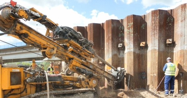
Within ground engineering, anchors can support sheet piling, secant pile walls or contiguous pile walls. Their inclusion depends on the excavation layout, ground conditions and available space beyond the retaining structure.
How Free and Bond Lengths Function
A conventional prestressed ground anchor has two distinct tendon zones: a free length and a bond length.
The free length extends from the head towards the anchoring zone. Along this section, the tendon is prevented from bonding to the surrounding grout so it can elongate during stressing. This arrangement allows tension to reach the intended load-transfer zone.
Within the bond length, force passes from the tendon through grout into the ground. For retaining applications, this zone is positioned beyond the potential failure surface identified by the design.
These lengths perform different tasks. Increasing steel capacity alone will not compensate for an inadequate ground bond or unsuitable anchoring position.
What Determines the Tendon Specification?
Specification brings together structural loading, ground investigation findings and practical installation requirements. Principal considerations include:
- Required tensile capacity: determines the bar size, number, and number of strands and strand grade.
- Anchoring conditions: influence the bond arrangement needed to develop resistance in soil or rock.
- Movement limits: affect the required free length and prestressing force.
- Access and handling: influence whether a rigid bar or flexible strand assembly is practical.
- Service life and exposure: establish the corrosion-protection requirements.
- Future below-ground works: may justify a purpose-designed removable or cuttable system.
Bar tendons can use threaded connections and couplers, while strand assemblies provide flexibility when handling longer anchors. Selection must also account for compatible anchor heads and stressing equipment.
How Are Tendons Installed and Stressed?
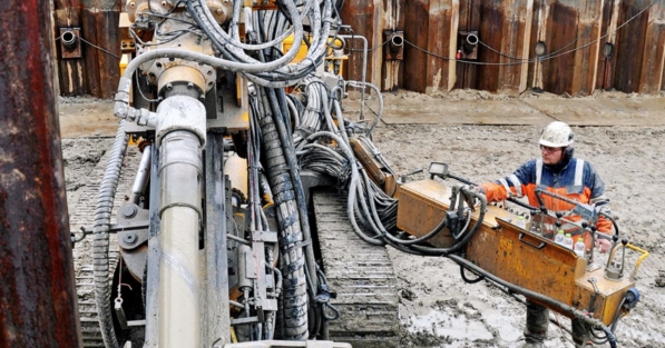
Before installation, the assembled tendon is checked against its specification, including dimensions, protective sheathing and connections. Spacers or centralisers help keep it in its intended position within the drilled hole.
Grouting then follows the selected anchoring method. The procedure must establish the designed bond while preserving freedom of movement along the free length. Details vary between systems, particularly where staged or repeat grouting is required.
Once the grout and supporting structure have reached the specified strength, a hydraulic jack applies tension at the exposed end. Testing records load and movement to assess the installed anchor’s response.
After acceptance, the tendon is secured at the specified lock-off load using the anchor head. Stressing records provide a reference for any subsequent checks included in the inspection plan.
Protecting Tendons Below Ground
Buried steel needs protection appropriate to its environment and intended working life. Depending on the system, protective measures can include grout encapsulation, plastic sheathing, corrosion-inhibiting compounds and sealed connections.
Continuity matters, particularly at couplers and where the tendon meets the anchor head. Damage during storage, handling or insertion can compromise an otherwise suitable protective arrangement.
Most of the tendon becomes inaccessible once installed. Checking its condition before placement, documenting construction and allowing for any specified monitoring therefore support long-term performance. These measures help preserve the connection the anchored structure relies on.

Written by Aarsleff UK
22 October 2026
Aarsleff Ground Engineering is a leading sheet piling supplier and contractor. We specialise in designing and delivering sheet piling solutions across the UK.

Reviewed by Mark Fuller, Piling Director
6 October 2026
Mark Fuller is the Piling Director at Aarsleff Ground Engineering. He has amassed a wealth of experience and knowledge within the specialist piling and ground engineering industry throughout his 20 years of experience in the industry. Mark is directly responsible for the overall driven piling within the business, including technical and operational management of awarded contracts, development of strategic long-term plans and planning of recruitment and resource.
Close