Channel Tunnel Rail Link / High Speed 1
DRIVING OF PRECAST PILES FOR HIGH SPEED 1 RAIL PROJECT

Project Description
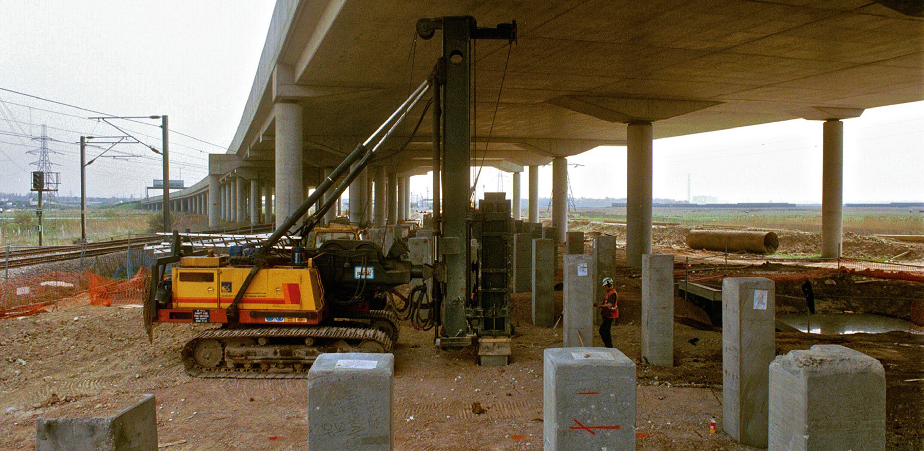
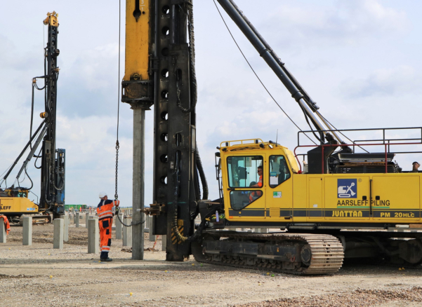
SCOPE OF WORKS 3,000 No. 600 x 600mm, L=9.5 – 18m precast reinforced concrete piles
CLIENT Morgan-Vinci JV
EQUIPMENT Hitachi KH180.3 GLSK, Aarsleff’s Low Headroom Rig
CONSTRUCTION PERIOD Jul 2002 – Jan 2004
Following the UK Government’s approval for two sections of 69-mile high-speed Channel Tunnel Rail Link (CTRL), now referred to as HS1, the project, specifically CTRL Contract 310 West Thames Ribble Lane to Thurrock, was put out to tender and awarded to main contractors Morgan-Vinci, as a joint venture.
This enormous and complex project required vast amounts of foundation works, including piles to support sections of the 7-km,10m-wide reinforced concrete track slab that carries the high speed line over the soft West Thames marshes at Havering an Thurrock, Essex, ground that can comprise up to 10m of alluvium over flood plain deposits, tertiary clays and sands or chalk.
Arrsleff’s tender was successful in winning the piling contract, valued at approximately £4.25M. The scope of the project was to install 3,000 specially manufactured 600mm x 600m square section precast concrete piles, in lengths varying from 9.5m to 18m in rows of four and six at 5m centres, to support the reinforced concrete track slab.
With the estimated 18-month project commencing in July 2002, work on casting the 600mm square section continuously reinforced concrete piles began in June 2002.
The Piles were cast using Centrum Pile’s proven free-flowing, self-compacting concrete mix, which does not require any vibration, flowing into the moulds and around the rebar, which had a tried-and tested history having been used previously in the manufacture of the company’s smaller, standard square section reinforced precast concrete piles.
Additionally, the CTRL piles also incorporated full length chamfered corners and domed heads, typical of Centrum Pile’s standard design features, which eliminated the need for reinforced bands required for driving conventional flat-topped piles.
The perfectly symmetrical 600mm square section piles were cast in 14.2m long single length segments, which weighed 12.5 tonnes using purpose built moulds. A special rigid mechanical joint was also cast into the ends of some piles to achieve the necessary 18m maximum length required on site.
The sections of the steel moulds were individually formed and separated between each section and a combination of cams and hydraulic rams locked the sides of the moulds in the vertical during casting.
Case Study
Please enter your details to download this document
The Latest. News, podcasts & projects


