What is Jet Grouting?
Jet Grouting and Its Ground Function
Jet grouting is a ground engineering technique that uses high-energy fluid jets to break up soil and mix it with a cementitious grout. Once cured, this mixture forms a soilcrete body within the ground. Engineers use jet grouting to improve ground strength, reduce permeability and provide support for excavations, foundations and existing structures where conventional ground improvement methods may not be suitable.
Columns can be installed individually or arranged to overlap, creating a larger treated mass, wall, slab or plug.
Unlike permeation grouting, which introduces grout into available pores and voids, this method deliberately erodes and remoulds surrounding material. Treatment geometry therefore comes from a controlled combination of drilling, jet pressure, rotation and withdrawal. Design can target greater strength, lower permeability, improved stability or a combination of those functions.
How Soilcrete Columns Are Formed
Installation begins with a small-diameter bore advanced to the base of the proposed treatment depth. A monitor fitted with nozzles sits at the end of the drill string. During withdrawal, high-velocity jets erode adjacent soil while grout mixes with loosened particles. Controlled rotation spreads treatment around the bore, usually producing a broadly cylindrical column.
Spoil slurry returns towards the surface through the annular space around the drill string. Maintaining that return path matters: an interruption may allow pressure to build underground, creating a risk of ground movement or unintended grout migration. Site teams monitor the process and manage arisings as part of installation.
Jetting systems are commonly described as follows:
- Single-fluid treatment uses a grout jet for both erosion and mixing.
- Double-fluid treatment adds compressed air around the grout jet to extend its cutting action.
- Triple-fluid treatment separates erosion by water and air from subsequent grout injection.
Selection depends on the ground profile, required treatment diameter, strength criteria, environmental constraints and nearby assets. A trial installation may be used to refine the working parameters before production starts.
Equipment Behind Controlled Treatment
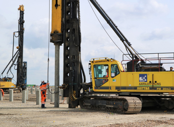
A jet grouting rig provides drilling, rotation and controlled withdrawal. Its size and configuration must suit access, headroom, treatment depth and the required drilling alignment. Projects within basements or existing buildings may call for compact plant; open sites can accommodate larger units.
Beyond the jet grouting machine itself, a complete setup includes a grout batching and mixing plant, high-pressure pumps, cement storage, air compressors where required, hoses, spoil-handling provisions, and process-monitoring instruments. This supporting jet grouting equipment has a direct bearing on consistency. Stable grout properties and recorded operating parameters help connect the design assumptions with the installed work.
Modern control systems can capture values such as depth, rotation rate, withdrawal speed, grout flow and injection pressure. Operators use those readings to identify deviations during construction. Records also provide a traceable account for each treatment position, although logged data does not replace the physical verification of finished soilcrete.
Where Jet Grouting Adds Project Value
Jet grouting serves projects across infrastructure, energy, residential, rail, commercial, marine and cultural markets.
- Within infrastructure, it may support work around bridges, tunnels, highways, deep excavations and buried services.
- Energy schemes can use treatment around operational facilities or new foundations.
- Rail projects may require local ground improvement beside tracks, stations, structures and embankments.
- Residential and commercial developments often consider it where basement construction, constrained sites or neighbouring buildings limit conventional approaches.
- Marine applications may involve ports, harbours, quay structures and waterfront excavations where ground stability or groundwater control is required.
- Cultural projects, including museums, galleries and heritage buildings, may benefit from treatment that can reach beneath or beside sensitive existing structures.
Jet grouting underpinning uses soilcrete beneath or alongside an existing foundation to improve support or to transfer loads into treated ground. Careful sequencing, connection design and movement monitoring become especially important when occupied or sensitive buildings remain nearby. Since treatment does not address every cause of settlement, engineers assess the foundation condition, load path and surrounding geology before selecting an arrangement.
Restricted access can also influence that choice. Comparatively slender drill strings reach treatment zones from a limited working platform, and column spacing or orientation can be adapted to suit site geometry. Inclined or horizontal installation may be considered where conventional vertical treatment cannot reach the required area, subject to specialist planning, suitable plant and a defined verification strategy.
When is Jet Grouting Used?
Engineers may specify jet grouting where conventional ground improvement methods cannot provide the required combination of strength, groundwater control or construction flexibility. Typical applications include deep excavations, basement construction, underpinning, tunnel works, retaining structures and projects where restricted access or nearby buildings limit the use of larger foundation systems.
Ground Conditions Shape the Design
Jet erosion behaves differently across sand, gravel, silt, clay and made ground. Dense layers, cohesive pockets, cemented material or buried obstructions can reduce the achievable diameter or produce irregular boundaries. Groundwater conditions may affect spoil returns, grout behaviour and the means needed to control inflow.
A geotechnical investigation should establish the relevant strata, strength, variability, groundwater levels and potential obstructions. Laboratory testing can help assess grout mixes, but field trials often provide more direct evidence of the achievable geometry and soilcrete properties. Column layout then needs to account for positional tolerance, verticality and likely variation with depth.
Suitability also rests on what surrounds the treatment area. Utilities, drainage routes, adjacent foundations and environmentally sensitive receptors require consideration. Where overlapping columns form a barrier, small gaps may compromise performance; where columns carry structural load, strength alone does not define behaviour. Stiffness, continuity and load transfer remain part of the design.
Verification From Trial to Completion
Quality management starts before production. A project specification should define performance criteria, acceptable materials, installation parameters, tolerances, monitoring arrangements and testing frequency. Trial columns can be exposed, cored or otherwise examined to compare the proposed settings with the actual ground response.
During the work, crews review drilling and jetting records, grout consumption, spoil return and any signs of movement. Instrumentation may be introduced near sensitive buildings or excavations. If recorded values fall outside the agreed limits, treatment can be paused while the cause and corrective action are assessed.
Completed work may be checked through coring, laboratory strength or permeability tests, a geometric investigation and a review of continuous installation data. Appropriate methods depend on the intended function. A groundwater cut-off, for example, calls for evidence different from that required for a load-bearing element.
Properly designed treatment brings together investigation, calibrated construction parameters and proportionate verification. That joined approach explains both the capability and limitations of jet grouting: performance comes from controlled execution in known ground conditions, supported by evidence from the installed works.

Written by Aarsleff UK
22 September 2026
Aarsleff Ground Engineering is a leading sheet piling supplier and contractor. We specialise in designing and delivering sheet piling solutions across the UK.

Reviewed by Mark Fuller, Piling Director
21 July 2026
Mark Fuller is the Piling Director at Aarsleff Ground Engineering. He has amassed a wealth of experience and knowledge within the specialist piling and ground engineering industry throughout his 20 years of experience in the industry. Mark is directly responsible for the overall driven piling within the business, including technical and operational management of awarded contracts, development of strategic long-term plans and planning of recruitment and resource.
Close